KC5LDO
6DQ6 Novice CW Transmitter and Power Supply
While searching for a new transmitter project that provided higher output and
band switching, I came across an article in the QST archives. The December
1957 issue of QST describes a three band novice transmitter that met the above
requirements plus included the 15 meter band.
A quick check of the schematics showed no unusual parts as most are readily
available. The original schematic included a power supply and side tone monitor in
one enclosure. Since I have several power supplies and use a receiver to monitor
my signal, I excluded the power supply and side tone monitor. This simplified
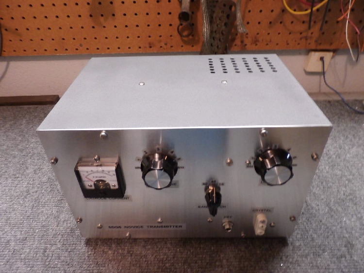
construction and meant the transmitter could be built in an EICO 377 audio generator
cabinet I had on hand. The EICO cabinet measures 11" wide by 7" tall and 7 3/4"
deep. I used the EICO cabinet and chassis while adding a new front panel.
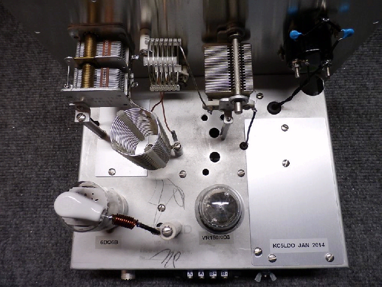
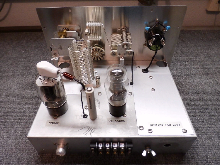
The transmitter uses a 6DQ6B tube with an OD3 regulator to regulate screen voltage.
Regulated screen voltage minimizes chirp and ensures the best keying characteristics.
The original schematic used a 3-30 PF trimmer capacitor between pins 5 & 8 of the 6DQ6B.
In its place I used a fixed 10 PF capacitor. I was lucky to find the B&W 3018 coil stock that
the article called for. Coil specifications are included in the schematic, should you choose
to build your own coils.
Fundamental crystal frequencies are used for the 80 and 40 meter bands. For 15 meter
operation 40 meter crystals are used on their third overtone. I've had no problems using FT-243
crystals. Power output is consistent with great keying characteristics.
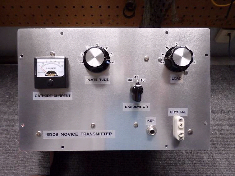
Through experimentation I discovered that the only way to properly tune for maximum output
is by using a wattmeter. I found it difficult to tune the transmitter using the cathode current
meter. The old method of tuning for maximum light bulb brilliance works as well, Although the
transmitter uses a pi network output that tunes easily, I found that using an antenna tuner
yielded slightly more output.

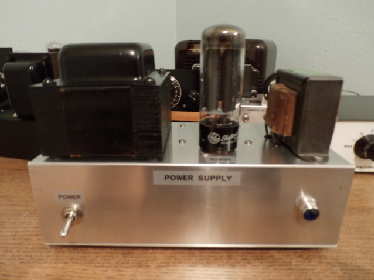
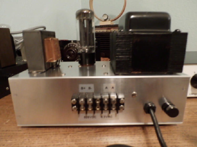
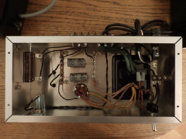
The power supply schematic shown utilizes full wave 5U4GB rectifier with capacitor input
filtering. Final output voltage will vary depending upon your choice of transformer. Any well
filtered power supply that provides between 375 VDC and 475 VDC @ 125 ma. will work
well. Voltages quoted here are to be measured with the power supply on and connected to the transmitter while it is
"unkeyed". Transmitter and power supply voltages can be LETHAL. If you are not familiar with high voltage power supplies, please seek experienced
help.
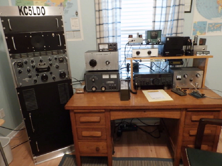
This was a challenging and fun project that will provide years of enjoyment.
The 6DQ6 will likely find a permanent place on my main radio operating desk.
73, James, KC5LDO
Articles written by James Tobola - KC5LDO
and reproduction, publication, or duplication of this article, or any part thereof,
in any manner is prohibited without the express written permission of the author.
©2014

Thank you for visiting our page and please sign with your comments into the

Guestbook
or drop us an

w5dxs@hotmail.com


 These Web Pages were created by using 100% Recycled Electrons. These Web Pages were created by using 100% Recycled Electrons.
|