The KC5LDO
6SL7 Twinplex Regenerative Receiver
The regenerative receiver was very popular among shortwave listeners and
amateur radio operators during the 1930s to the 1950s. Their popularity
diminished with the availability of war surplus receivers and low cost
commercial receivers. Many circuits were designed using various tube
types ranging from excellent performers to dismal at the best.
Successful operation of a regenerative receiver requires patience and sharp
tuning skills. Neither is difficult to obtain when using a well designed circuit.
The 6SL7 Twinplex is an excellent circuit that delivers selectivity, sensitivity and
stability. Careful planning in construction will yield surprising results. The Twinplex
has great audio for AM reception as well as tuning SSB and CW signals easily.
The 6SL7 tube is a dual triode with one section serving as detector and the
other section as audio amplifier. The 6SN7 tube is also very popular in this
circuit while having a lower amplification factor. The 6SL7 tube has an
amplification factor of 70 while the 6SN7 has a factor of 20. After my
experimentation with both types I prefer the 6SL7. Which tube is used is a
matter of personal preference.
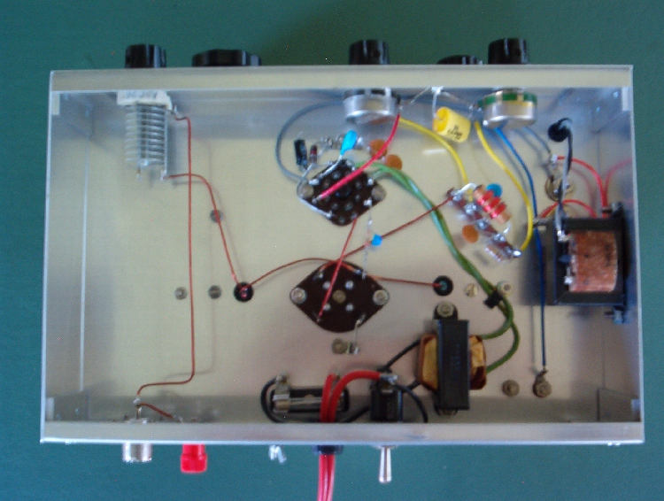
Hand capacitance can be a problem with any regenerative receiver, but can be
eliminated with proper construction techniques. Using a metal chassis with a
metal front panel is a must while also using a good ground connection. The chassis
size measures 7x11x2 inches. Shaft insulators are required for both tuning
capacitors. All of the knobs should be nonconductive such as Bakelite or plastic.
Many regenerative receivers use vernier dial drives for bandset and bandspread
controls. Some type of vernier dial is necessary for bandspread control. Simply
using a large graduated dial for the bandset is sufficient. The bandset control
is used to set the receiver to a particular part of the band. The bandspread control
is then used for fine tuning. Slow turning is required for both controls. Stations
can easily be skipped over if tuning is not done slowly.
Parts values shown in the schematic are the exact values I used. Performance
of my set was so impressive that I never experimented with any other values.
The odds are that anyone wanting to build this set would have the exact same
variable capacitors that I used will probably be slim. A slight variation in the
variable capacitors is acceptable. Using capacitors with a slightly different
value will only effect the tuning range.
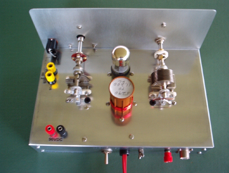
I used Bud 4 pin plug-in coil forms measuring 1 1/4 inch diameter. The coil
winding information is to be used as a reference only. Frequency coverage will
vary depending on the variable capacitors used and construction techniques.
I modified my coils four times before being satisfied with the frequency
range. Use enamel covered wire that is 22 ga. to 24 ga. in diameter. This is
equivalent to .025 to .020 of an inch respectively. All windings are close wound
with .100 of an inch between tickler and tuning coil. It is important to wind both
coils in the same direction. Tickler windings are wound on the bottom of the
coil form with the tuning coil on top.
My first coil has a frequency coverage of 5290 to 11,200 kc using 3 turns for
the tickler and 10 turns for the tuning coil, My second coil covers 8510 to
18,000 kc using 2 turns for tickler and 5 turns for tuning coil. If you cannot
get your set to go into regeneration try removing one turn from the tickler coil.
Adding turns to the tuning coil will lower the frequency coverage while removing
will raise the frequency coverage. It is important to note that adding or removing
one turn will make quite a difference. Many times a 1/2 turn is all that is needed
to obtain the frequency coverage required. Once you have obtained the
frequency coverage desired, glue the windings in place as any movement will
alter frequency coverage.
When choosing an antenna it is important to remember that it is part of the
receiver circuit. If the antenna is too long the signals will be loud, but you will
lose selectivity, sensitivity and regeneration control. This happened with my set
when I tried a 60 foot random wire antenna. Most regenerative receivers are so
sensitivity that only a 25 ft. to 35 ft. random wire antenna is needed. When the
correct antenna is used regeneration will be smooth and the set will be very
selective.
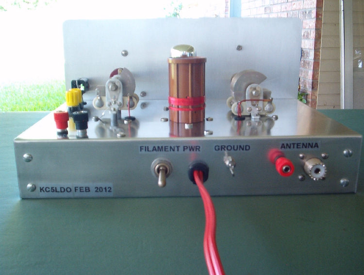
The antenna trimmer capacitor is an important part of the Twinplex circuit.
If the antenna is coupled too tightly the set will most likely not go into
regeneration. Use just enough coupling to give smooth regeneration control.
This is usually in the range of 2pf. to 10pf., which means, the plates of the
trimmer capacitor will only be sightly meshed. This adjustment will rely greatly
on your antenna. Patience and experimentation will pay off here.
Powering the Twinplex is not complicated. The 6SL7 and 6SN7 filaments require
6.3 volts. The 6SL7 filament draws .3 amps. and the 6SN7 filament draws .6 amps.
Because of this amp draw it is easier to use a filament transformer and power the
filaments with A.C. The filaments can be powered by battery, but battery life would
be limited due to the higher current drain. The "B" supply consists of ten 9 volt
batteries connected in series to produce 90 volts. The set will operate with lower
voltages, but the volume will be lower. The "B" battery current drain is only 2 to 3 ma.
Battery life is very good and it should be disconnected when not in use.
The Twinplex circuit is designed to use high impedance headphones. Older
headphones with 2000 ohms impedance or higher may be used. I originally
used a pair of Trimm Professional headphones which worked very well. I
decided to use lighter and more comfortable, modern headphones which have
an impedance of 8 ohms. To use the newer headphones an audio matching
transformer is needed to match the high impedance required of the receiver to
8 ohms. Connect the high impedance side of the audio transformer to the phone
terminals in the schematic. The low impedance side of the transformer is
usually for 8 ohm headphones. It is EXTREMELY IMPORTANT to note
that all of the headphone connections must be insulated from the chassis. After
experimenting with several sets of headphones I chose a pair of Yaesu YH-55.
They are excellent at hearing weak signals and comfortable.
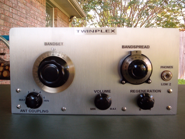
When you first try out your receiver, set the controls as follows: antenna trim
and volume to midway; regeneration to 9 o'clock position; bandset and
bandspread capacitors slightly unmeshed. Connect your antenna, ground,
headphones, battery pack and turn on the filament power. Allow tube to warm
up for a minute. Adjust regeneration until you hear a click or hissing sound.
The set is now in oscillation. The point where oscillation just begins is when
the receiver is the most sensitive. Turn the bandset control slowly until you
either hear a station or a squealing sound which is a heterodyne. Adjust the
regeneration until squealing stops and you should hear a station. Use the
bandspread to tune your stations. Adjust volume and regeneration for best
reception.
These tips will help you get started with your new receiver and please remember
the word, "patience", as mentioned earlier. Using a regenerative receiver takes a
little getting used to. I call the Twinplex a real radio because it has five controls
and you actually use all five during operation . A hands on radio for sure.
73, James, KC5LDO
Articles written by James Tobola - KC5LDO
and reproduction, publication, or duplication of this article, or any part thereof,
in any manner is prohibited without the express written permission of the author.
©2013

Thank you for visiting our page and please sign with your comments into the

Guestbook
or drop us an

w5dxs@hotmail.com


 These Web Pages were created by using 100% Recycled Electrons. These Web Pages were created by using 100% Recycled Electrons.
| 