
W5DXS - Heart Of Texas DX SocietyHOTDXS WORKBENCH |

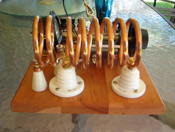
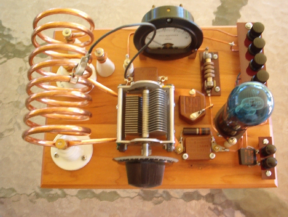
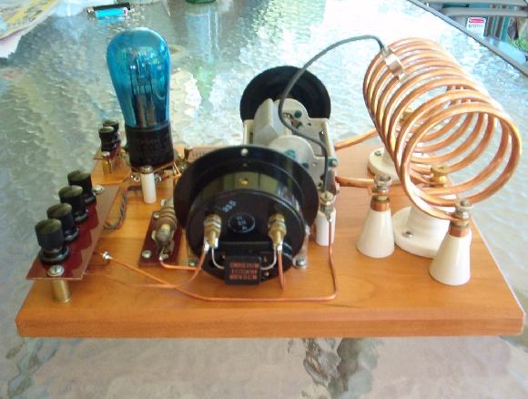
The KC5LDO 1929 Hartley TransmitterI have always been fascinated with anything that relates to radio. My main interest is the tube type equipment ranging from the 1920s to 1960s. The very early receivers and transmitters have always caught my eye because they look so impressive. Some certainly look dangerous and this alone should spark some interest. Hi Hi I always thought these old transmitters could not be put on the air anymore. I learned about the "Antique Wireless Association" and the special events they have for such transmitters. Here is a link to an excellent article written by Scott, WA9WFA titled "Building A 1929 Style Hartley Transmitter". I must also give thanks to Nick, WA5BDU for his article "My 1929 Hartley Transmitter". These were the basis for my transmitter. A few words of caution. These transmitters and power supplies both have LETHAL voltages in them. All components are exposed which can make them dangerous if caution is not observed. DO NOT build or operate this style of transmitter unless you fully understand this. If you are not sure of something, ask for help. Be careful and do not second guess. After searching through my junk boxes I was surprised to learn I had about 90% of parts needed. Parts value can vary slightly and not effect performance. I followed the schematic in the above mentioned articles with one exception. I added a 0-50 milliamp D.C. meter in series with the B+ supply making tune up easier. I tried to use period parts and some are not, but look like they belong. Hi Hi The wood base is a 9 X 12 inch plaque and is 3/4 inch thick. I am not sure what type of equipment the rest of the parts came from. The coil is made from 1/4 inch copper water line for refrigerators. My coils are wound for 40 meters and are 3 inches in diameter. Spacing between the beehive insulators is 4 inches. The space between the tank coil and link coil is 3/4 inch. You have to experiment with this spacing for best output and tone. The variable capacitor I used has 18 plates in the rotor, but would not tune all the way down in the 40 meter band. It was necessary to add a .0002 mfd. fixed capacitor in parallel with the variable capacitor. It easily tunes all of the 40 meter band now. All wiring is 12 ga. house wiring. The only exception being the filament wiring. It is 16 ga. cotton covered and twisted because the filament voltage is A.C. All other wiring needs to be stiff because these transmitters are very sensitive to vibrations and any movement.To reduce this problem I used soft rubber feet on the bottom of the wood base.
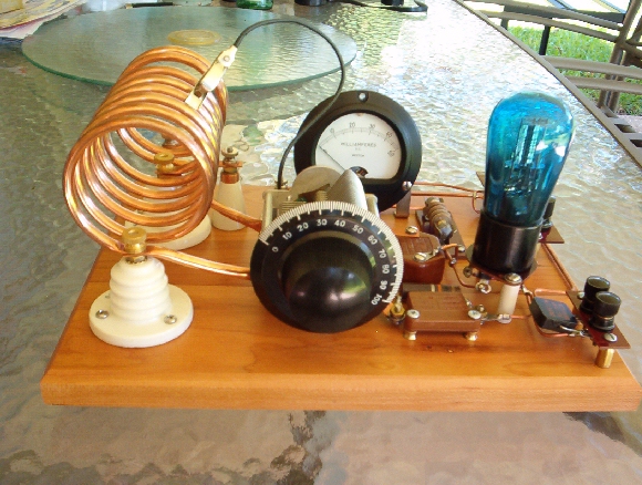 The type 27 tube was used as a receiving tube, but it makes a nice oscillator. They come as balloon or shoulder shape. I prefer the balloon tube. The tube pictured is a blue Arcturus brand. They require 2.5 volts for the filament at 1.75 amps and a plate voltage of around 250 VDC. Use a well filtered power supply. I will discuss power supplies at a later date. All other hardware came from the junk box. Use your imagination and have fun with it.
 The tune up is fairly easy, but will require some experimentation. Leave the two turn link coil off and do not attach an antenna for now. To listen to the Hartley's signal I used a small portable S/W receiver set at 7.050 MHz. I set it about 10 feet away from the Hartley. I put the ground clip on the 4th coil and slowly tuned until I heard the signal.
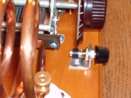
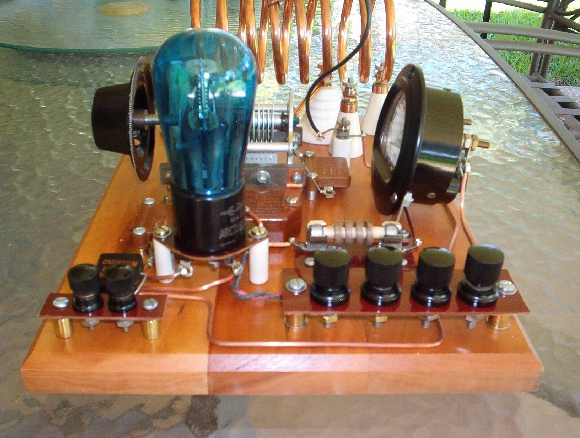 Once you have found the signal you can adjust the tap for the best tone and output. Turn the power off before moving the clip. Remember the LETHAL voltages. The alligator clip shown in the pictures is where mine works the best, Tune the variable capacitor slowly as adjustment is very touchy. A vernier dial would have helped, but it is not necessary.
 After you have the Hartley sounding its best you can add the link coil and attach to an antenna. This is where you may have to experiment with the spacing between the tank and link coils. Set the spacing for the best output. Due to body capacitance it's best to have the transmitter two or three feet away from you.
 I used a shortened 40 meter dipole mounted in the attic so I don't have to worry about wind moving the antenna and making small changes in the frequency. Output is 2 to 2.5 watts and sounds very good. It has a unique tone, but it is easy to listen to. There is no doubt that you can recognize it as being a Hartley. 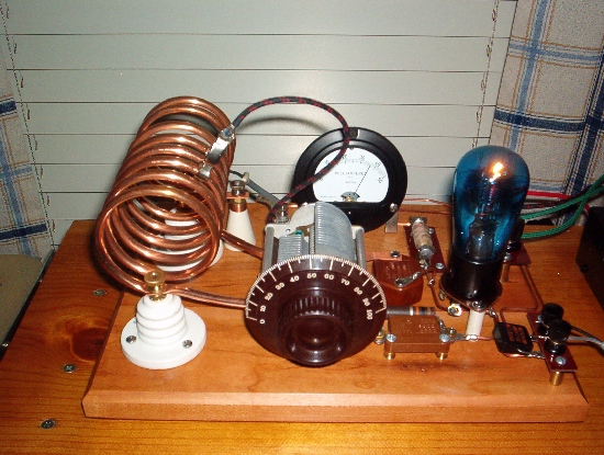
The above picture is the 1929 Hartley Transmitter with the 27 tube fired up at 36 ma and using
a Type 80 Tube Power Supply. Below you will find a link to this power supply that is a perfect
mate for the 1929 Hartley Transmitter.
It was a fun project and certainly made me appreciate all the old timers and their ingenuity. 73, James KC5LDO Update to the 1929 Hartley Transmitter
|
Return to the Table of Contents |


 These Web Pages were created by using 100% Recycled Electrons.