

 
W5DXS - Heart Of Texas DX SocietyHOTDXS WORKBENCH |
KC5LDOT - Network TunerI have been using L type tuners for a couple of years with great success. Due to the L tuner limitations, I had designed mine primarily for the low bands. I decided to build a T network tuner that would allow operation on the lower bands as well as the higher bands. Plans were to build a Kilowatt tuner that would safely handle the output of my Ameritron AL - 811 H amplifier.
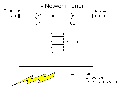 The T tuner is a simple design employing two variable capacitors and one inductor. For simplicity I choose to use a tapped inductor. The inductor came from surplus equipment and measures 2" by 5". It has 41 turns of silver tinned wire tapped at 3, 9, 17, 20, 28, 31, 34 and 37 turns. Approximate inductance is 40uh. The heavy duty ceramic rotary switch contains silver contacts. 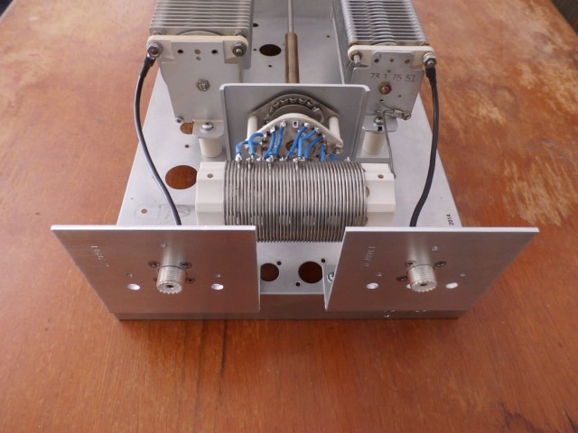 The variable capacitors I used were chosen because of availability. The input capacitor measured 400pf. and the output capacitor measured 500pf. Both have .075 plate spacing. It is important to note that both capacitors and their shafts are insulated from the chassis. 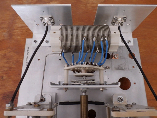 Since a Kilowatt tuner requires large components, finding a suitable cabinet for a reasonable price can be a problem. After searching and considering my options I discovered that old test equipment can usually be bought cheaply. I found a Bell & Howell model 34 oscilloscope that met my needs. The cabinet measures 12" wide by 16" deep and 8" high. I made a new front panel and used the scope's original chassis for the tuner. The scope provided many spare parts for future projects and the cost was $25.00. 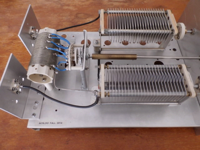 The T - Network tuner project was successful in that it allows me to use the amplifier if needed, on all of my favorite Ham bands. The rest of the story can be found in these pictures that will tell it much better than words. 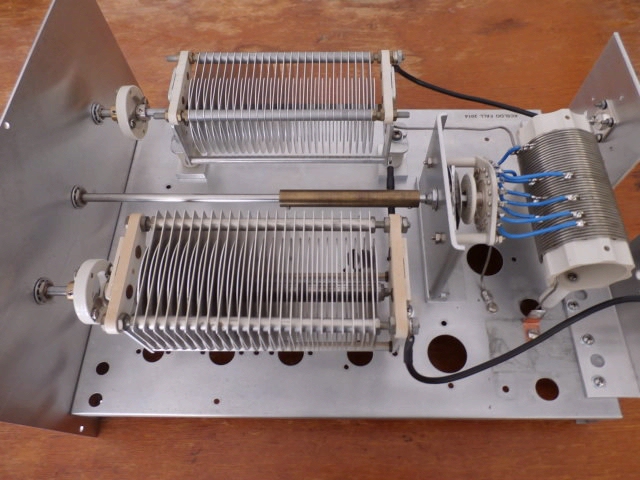 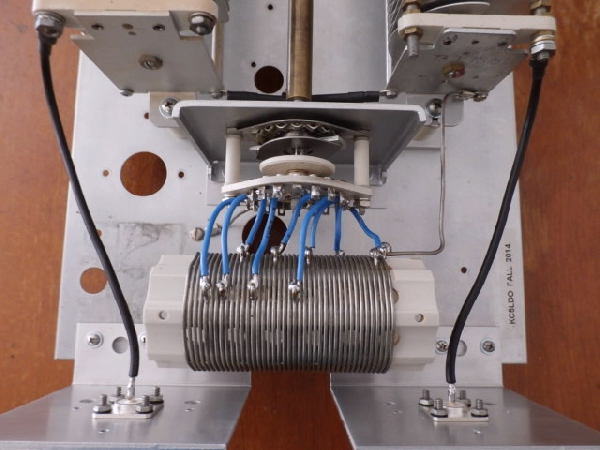 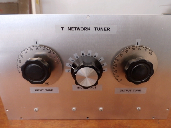 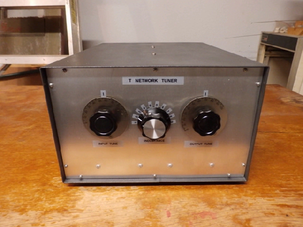 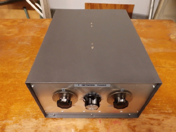 Many amateur radio operators will argue that an antenna tuner wastes power. This is not always the case with a tuner of good design. Many of the problems associated with tuners are due to operator error. Most tuners will provide a match using several different settings of the inductor and capacitors. Using the incorrect setting can cause loss and component heating. The best setting is one that uses the least amount of inductance and maximum capacitance. Example, if you can obtain a match by using either 3 or 5 turns of the coil then you should use the 3 turn setting. Maximum capacitance simply means keeping the variable capacitor plates meshed as much as possible. The T tuner will allow a match with several different settings. Following the above will give you the most efficient transfer of power. The T - Network Tuner RevisitedThis is another version of the T - Network Tuner. The only difference is that this one is made for 200 watts maximum. Sometimes SMALLER is BETTER and this little brother to the big one shown above just might be the one that will meet your needs. Here are the specs: 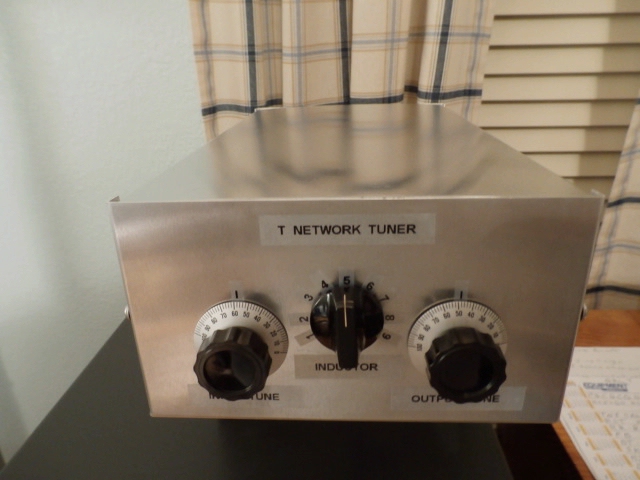 Chassis size: ( 12" deep ) X ( 7" wide ) X ( 4" high ) 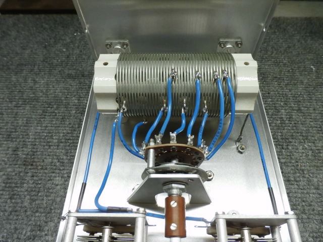 Variable capacitors: C1 and C2 are 330pf. with .020 of inch plate spacing. 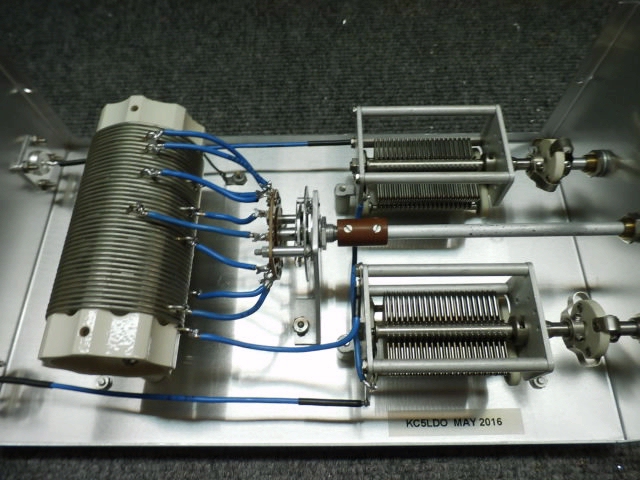
Coil info is 2in. diameter with 42 turns of #16ga. silver tinned wire. 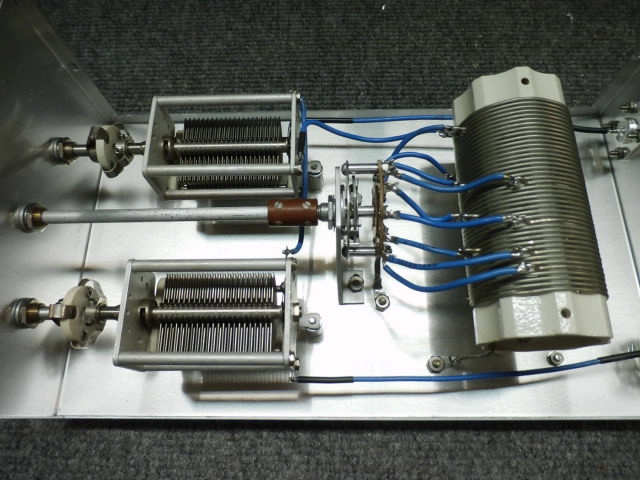 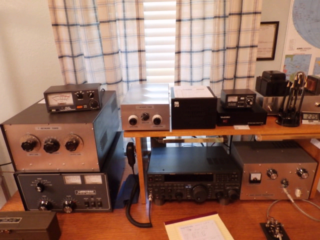 The finished "smaller tuner" project fits nicely on a full and busy desk. So, no matter if your pleasure is the bigger QRO tuner or the smaller QRP+ tuner, if you are looking for a real good T - Network Tuner, then either one of these projects should meet your needs. Foremost is to enjoy the building of projects and I hope we meet on the air.
Articles written by James Tobola - KC5LDO
|
|